EMC Compliance for Energy Meters: the invisible problem that kills projects
A meter that measures accurately on the bench can fail in the field without a single component breaking. The readings drift unexpectedly. Communication drops. A nearby variable-speed drive starts and the display freezes. Nothing is damaged, but the product does not work.
The cause is almost always electromagnetic interference, and the root cause is almost always a design that treated EMC as a test to pass at the end, rather than an engineering discipline applied from the start.
Two separate problems: emissions and immunity
EMC compliance covers two distinct requirements, and they demand different engineering responses.
Emissions are what the meter puts out. Every switching power supply generates conducted noise back into the mains and radiated noise into the surrounding environment. If that noise exceeds the limits defined by the applicable standard, the meter is non-compliant regardless of how accurately it measures.
Immunity is what the meter must withstand from the outside. Electrostatic discharge from a technician’s hand. Electrical fast transients from a contactor switching in the same panel. A high-energy surge coupling into the power lines during a lightning event. The meter must continue to function correctly through all of these not just survive but maintain measurement accuracy.
A design that passes emissions testing but fails immunity is a meter that works in the lab and fails in the cabinet. A design that passes immunity but exceeds emission limits is a meter that cannot be legally sold. Both sides must be solved simultaneously, and the solutions often conflict with each other.
The switching power supply: primary noise source
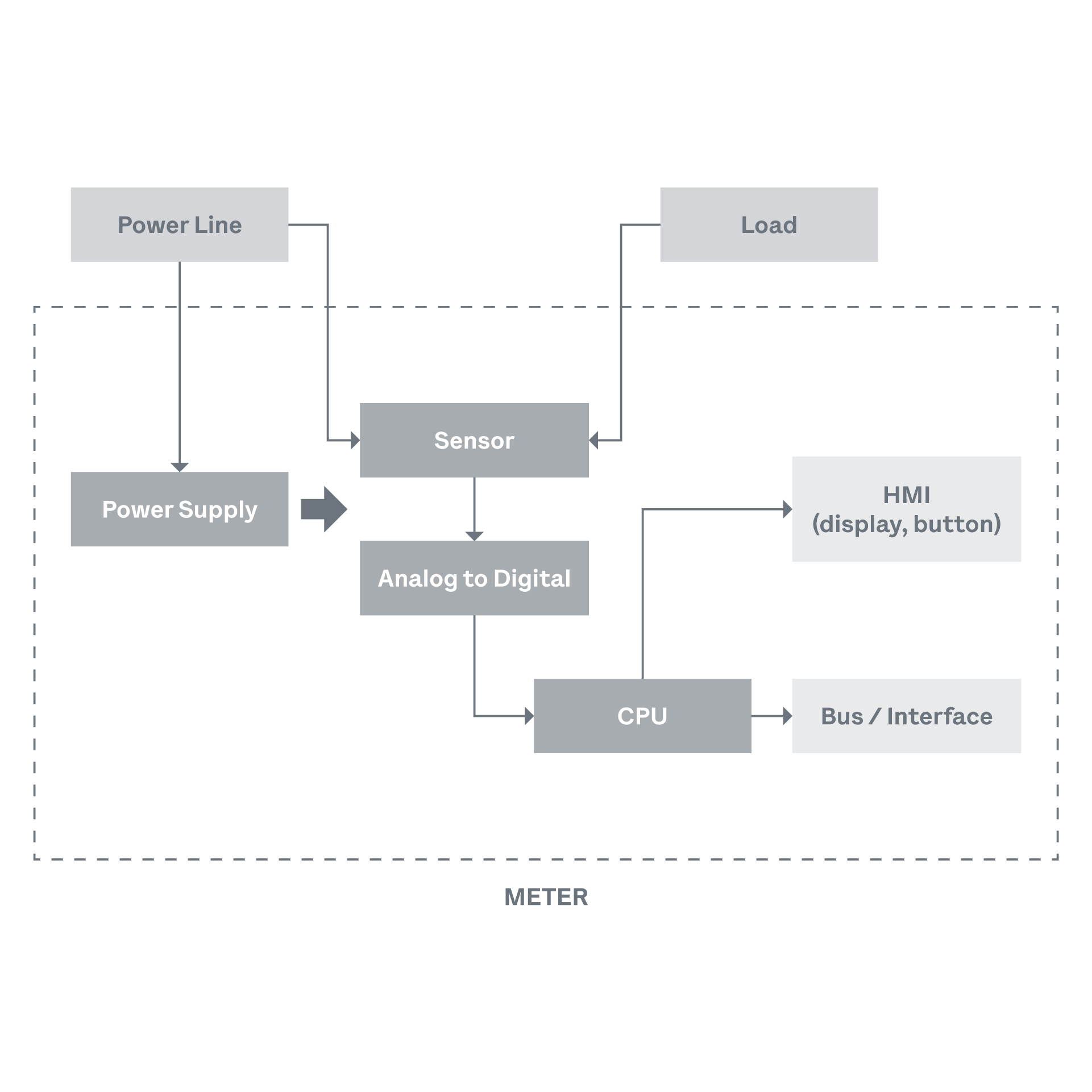
In most energy meter architectures, the internal switch-mode power supply is the dominant source of conducted emissions. It converts mains voltage to the low-voltage rails that feed the microcontroller, ADC, and communication interfaces. The switching action typically between 50 kHz and several hundred kilohertz generates harmonics that propagate back through the power input and radiate from PCB traces and internal wiring.
The standard countermeasure is an input EMI filter built from common-mode chokes and a combination of X-class and Y-class capacitors. X capacitors suppress differential-mode noise between line and neutral. Y capacitors suppress common-mode noise between line and earth. The choke impedance must be selected to attenuate the specific frequency range of the switching harmonics a generic filter copied from a reference design will not necessarily work for a different converter topology or switching frequency.
In a three-phase meter, this problem multiplies. Three active lines, each potentially carrying switching noise, and the possibility of parasitic currents coupling between phases through shared impedance paths on the PCB. The filter architecture must be balanced and symmetrical across all three phases. An asymmetry even a minor difference in trace length between filter stages can create a common-mode imbalance that converts differential noise into common-mode noise, which is far harder to suppress.
Immunity: surviving the real operating environment
The immunity requirements defined by IEC 61000-4-x test a meter’s ability to operate through specific types of disturbance.
ESD testing simulates the discharge from a human body or a charged object. Contact discharge at several kilovolts is applied directly to accessible surfaces. Air discharge at higher voltages is applied to points that might be touched during installation or maintenance. The meter must not reset, lose data, or produce erroneous readings.
EFT (electrical fast transient) testing simulates the high-frequency burst generated when inductive loads relays, contactors, motors switch on or off in the same installation. These bursts couple into the meter through its power input and, critically, through its communication ports. A meter installed in an industrial panel with multiple contactors will experience EFT events continuously during normal operation.
Surge testing simulates high-energy transients from lightning or major switching events on the grid. Unlike EFT, which is fast and repetitive, a surge is a single high-energy pulse that can physically damage components if the protection circuit is inadequate. The combination of metal oxide varistors, TVS diodes, and gas discharge tubes must be coordinated to clamp the voltage before it reaches sensitive circuits, while safely dissipating the energy without self-destructing.
In three-phase industrial installations, the severity of these transients is significantly higher than in single-phase residential environments. The energy content of a surge on a 400V three-phase supply is not simply three times the single-phase equivalent the coupling paths and fault modes are fundamentally different, and the protection strategy must account for both line-to-line and line-to-earth events.
PCB layout: where EMC is won or lost
The most expensive EMC filter in the world cannot compensate for a bad PCB layout. The board is the antenna, the coupling path, and the shield all at once. Layout decisions made in the first week of design determine whether the meter will pass EMC testing months later.
The foundational principle is the current return path. Every signal that travels from point A to point B must return from B to A. At high frequencies, the return current follows the path of lowest impedance, which is directly underneath the signal trace, through the nearest ground plane. If the ground plane is interrupted by a poorly placed component, the return current detours around the gap, creating a large loop that acts as both a transmitting and receiving antenna.
A proper design it costs nothing in components. It costs nothing in assembly. It requires only that the designer does not break it.
In a three-phase meter, the challenge becomes three-dimensional. Three sets of current inputs, three voltage sensing circuits, and the associated filter components must be arranged so that the magnetic field from one phase does not couple into the measurement path of another. This is a spatial problem that no schematic simulation fully captures it requires iterative layout, pre-compliance testing, and often physical rework on prototypes.
Cabling and mechanical integration: the last mile
EMC performance does not end at the PCB edge. The wiring between the meter and its installation power cables, communication cables, CT leads can act as antennas that pick up or radiate interference.
Long cable runs on communication ports (RS-485, M-Bus, Ethernet) are particularly vulnerable to EFT and surge coupling. The cable routing inside the electrical panel, the proximity to power conductors, and the quality of the cable shielding all affect the immunity performance of the complete installation. A meter that passes every EMC test in a shielded laboratory can fail in a panel where the Modbus cable runs parallel to a three-phase bus bar for 40 centimetres.
This means that EMC is not purely a product-level problem. It is a system-level problem, and the meter designer must anticipate the installation conditions. Port protection circuits common-mode chokes, TVS arrays, series resistors on communication lines must be designed with the worst-case installation in mind, not the test setup.
Pre-compliance and validation: testing before testing
EMC certification testing is expensive and time-consuming. A single failure at the accredited laboratory means a return to the design bench, a PCB revision, and a new test slot typically weeks or months of delay.
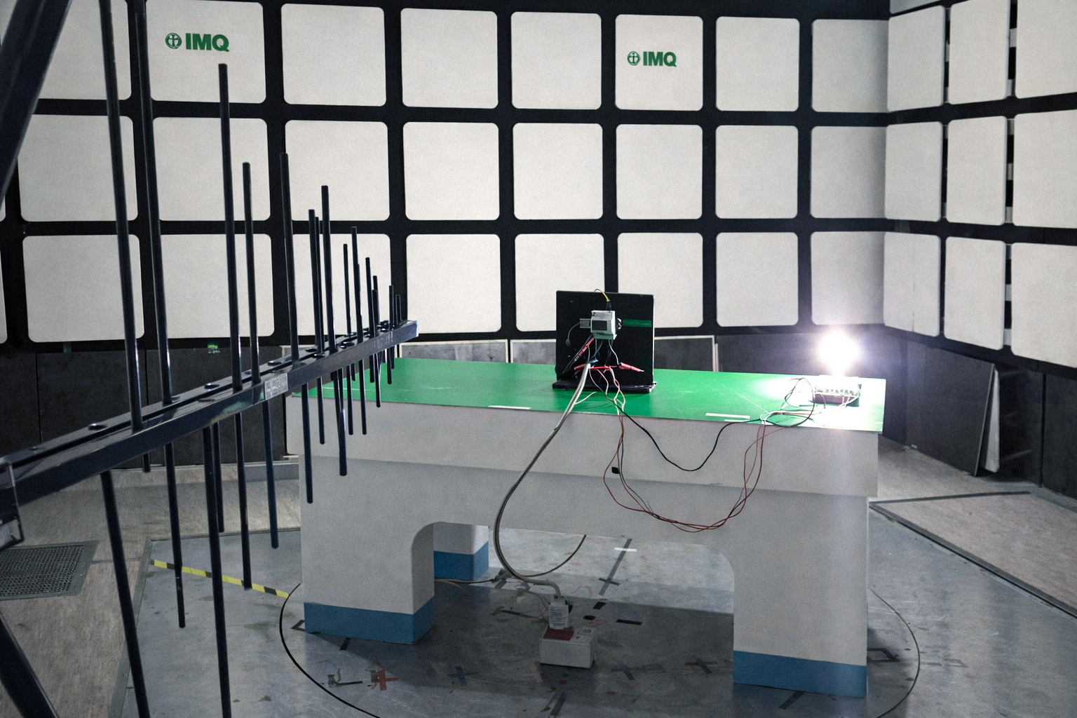
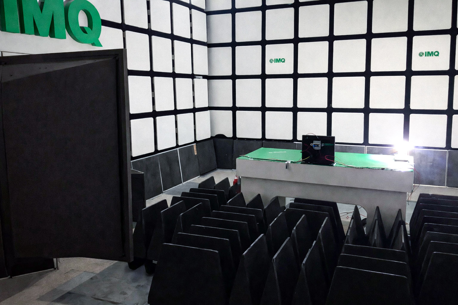
This is why pre-compliance testing exists. Before submitting the product to formal certification, the design team performs conducted and radiated emission scans, ESD walk tests, and EFT verification using internal or rented equipment. The goal is not to replicate the full certification test, but to identify problems early enough that fixing them is a layout change, not a product recall.
Pre-compliance is not a shortcut. It is a risk management tool. A supplier that routinely passes EMC certification on the first submission is not a supplier that got lucky it is a supplier with a mature pre-compliance process and the instrumentation to support it.
What this means for the OEM
When you integrate a third-party energy meter into your product, the meter’s EMC performance becomes part of your system’s EMC profile. Its emissions add to yours. Its immunity weaknesses become your system’s vulnerabilities. A meter that passes standalone EMC testing can still cause your product to fail system-level testing if the integration is not managed correctly.
The supplier’s role does not end at delivering a compliant component. It extends to understanding how that component will behave inside your enclosure, next to your power electronics, connected to your communication bus. A supplier that cannot discuss the EMC implications of integration trace routing, cable management, port protection, grounding strategy is a supplier that will leave you alone in the EMC chamber with a failing product and a deadline.
EMC is not a box to tick. It is a discipline that runs from the first schematic to the last installation. The meter is either designed for it, or it is not. There is no retrofit.