Thermal Management in Energy Meter Design: why your measurement element is also your biggest heat source
A unit passes all electrical tests at the bench. Accuracy is within spec. Certification is clean. Six months into field deployment, the readings start drifting. Nobody touched the firmware. Nobody changed the load profile. The meter simply got hot , and stayed hot.
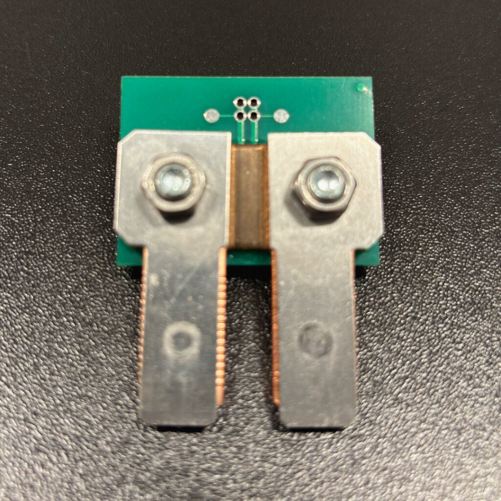
This is not a rare scenario. It is the predictable outcome of thermal design treated as an afterthought. In most electronics, the power supply is the dominant heat source. In an energy meter, it is not. The dominant heat source is the measurement element itself: the shunt resistor, the busbars, the PCB traces carrying line current. This changes the entire design logic.
The problem is physics, not negligence
Joule heating is proportional to the square of current: P = I²R. In an energy meter operating at 80 A with a shunt resistance of 0.5 mΩ, the power dissipated is 3.2 W, entirely concentrated in a component measuring a few square millimetres. That is not a component running warm. That is a localised heat source with a direct path to your accuracy specification.
The relationship between temperature and resistance is the core issue. Every shunt resistor has a temperature coefficient of resistance (TCR), expressed in ppm/°C. A shunt with a TCR of 50 ppm/°C operating 40°C above the calibration reference point introduces a 0.2% resistance shift. On a Class 1 meter, that alone can push you out of conformity, without any component failure, without any visible defect.
Low-TCR materials (such as Manganin or Zeranin alloys) reduce this effect, but do not eliminate it. Calibration at ambient temperature does not account for the thermal state the meter will operate in continuously. A design that ignores this is calibrated for the laboratory, not the installation.
The kelvin connection is not optional
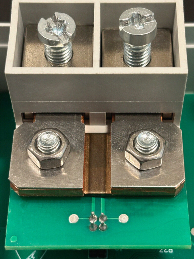
One design practice that separates competent thermal-electrical integration from basic assembly is the four-wire Kelvin connection. Two conductors carry the current. Two separate conductors measure the voltage drop directly at the shunt terminals, decoupled from the current path.
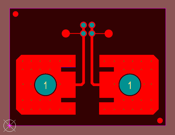
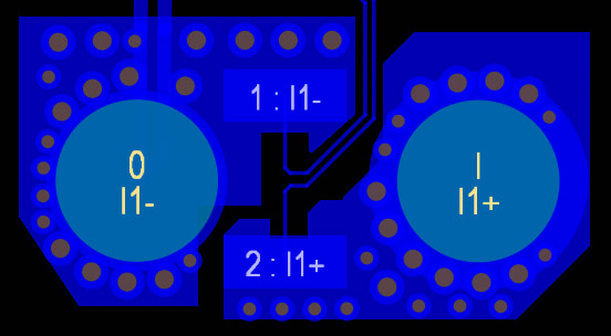
Without Kelvin geometry, the resistance of the PCB traces between shunt and measurement point adds to the reading. As those traces heat up, which they will, carrying high current, their resistance changes too. The meter is no longer measuring the shunt: it is measuring the shunt plus an unstable thermal artifact.
Kelvin layout requires deliberate PCB design decisions. It cannot be added after routing is complete. Specifying it as a requirement, and verifying it is implemented, is a check worth making when evaluating any meter supplier.
Three-Phase systems do not heat evenly
In a single-phase meter, thermal modeling is constrained to one current path. In a three-phase meter, there are three, and they do not behave symmetrically under real load conditions.
Industrial loads are rarely balanced. Phase imbalance as low as 10–15% is common in practice. That imbalance translates directly into uneven current distribution across the three measurement elements: one phase runs cooler, one runs hotter. The overall average temperature may appear acceptable. The hotspot on the overloaded phase will not be.
A design validated only under balanced three-phase load at nominal current is not fully validated. Worst-case thermal characterisation requires testing under realistic imbalance conditions, at maximum rated current, at maximum rated ambient temperature, simultaneously. This is the test that reveals whether the thermal margins in the design are real or assumed.
Terminals are where certification fails
The measurement circuitry is not the only heat-critical zone. Power terminals, the screw or spring connections where line conductors are physically attached, are a routine source of localised overheating in field installations.
Contact resistance at a terminal junction is not fixed. It varies with conductor cross-section, installation torque, conductor material, and surface condition. A connection that measures within acceptable resistance limits at assembly may develop a hotspot over months of thermal cycling. The IEC and UL standards that govern energy meters specify maximum surface temperatures accessible to users. Those limits are checked under certification conditions, which may not reflect the full range of installation quality encountered in the field.
The operating temperature envelope is expanding
Until a few years ago, 55°C maximum operating temperature was the standard specification for most industrial energy meters, sufficient for the majority of panel and switchboard installations. It no longer is.
Applications in EV charging infrastructure, industrial motor drives, and dense switchgear environments are pushing thermal requirements significantly higher. 70°C rated operation, once a niche requirement for special applications, is now increasingly treated as baseline. Some projects are beginning to specify 80°C.
This shift changes the design constraints substantially. A meter designed to operate reliably at 55°C ambient, with the thermal margins that implies, faces a fundamentally different engineering challenge at 70°C or beyond. Component selection, PCB layout, shunt alloy choice, and derating curves all need to be re-evaluated against the actual installation environment, not against the temperature rating that was standard when the platform was first designed.
Some meters on the market have responded to this by applying current derating at elevated ambient temperatures: the maximum measurable current is reduced as the cabinet gets hotter. This preserves component temperatures within limits, but it transfers the burden to the OEM integrator, who now has a meter that cannot operate at full rated current during summer peak loads in an enclosure without forced ventilation. It is a legitimate engineering trade-off, but it is a trade-off that should be understood before specifying the product.
What rigorous validation actually looks like
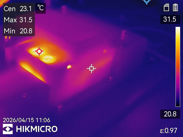
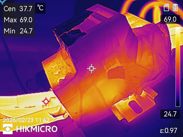
Simulation is useful for early design guidance. It is not a substitute for measurement. Thermal validation of an energy meter requires thermocouples placed at the shunt body, at the power terminals, at the ADC package, and at the enclosure surface, run continuously under worst-case conditions: maximum rated current, maximum rated voltage, maximum ambient temperature, maximum load imbalance for three-phase systems, sustained over time sufficient to reach thermal equilibrium.
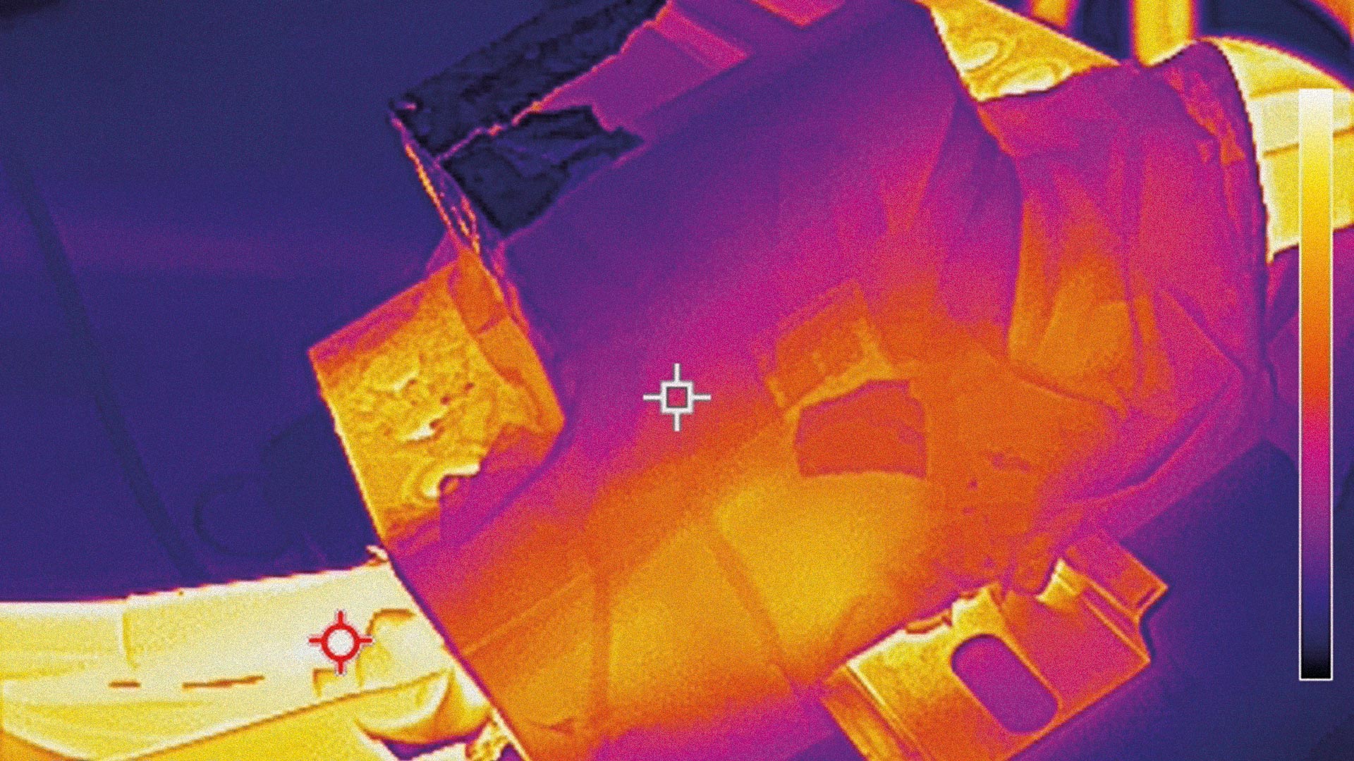
Thermal imaging adds the spatial dimension: it reveals hotspots that point measurements can miss, particularly at terminal interfaces and along high-current PCB traces. A thermal image taken during a certification run is not redundant documentation. It is evidence that the design margin is real.
Electrolytic capacitors are the canary. Their operational lifetime halves for every 10°C of sustained temperature increase above rating. A meter running 15°C hotter than its thermal design assumed does not fail the capacitors immediately. It halves their expected service life, and that manifests as field returns years into deployment, in volumes that are difficult to trace back to the original thermal model.
The question worth asking any meter supplier: what were the conditions of your thermal validation run, and do you have the measurement data? A supplier who tests at rated current with balanced load and ambient temperature of 25°C has characterised a best case. You will install the meter in a 45°C cabinet with an unbalanced industrial load. That gap is where field failures originate.
What this means for the OEM
Thermal performance is not a fixed product attribute that you read from a datasheet and assume applies to your installation. It is the outcome of a design process, one that must account for your specific current profile, your enclosure geometry, your ambient conditions, and the load imbalance characteristics of your application.
This is the conversation that should happen before a meter is specified, not after the first field complaint. The right question to a meter supplier is not “what is the maximum operating temperature?” The right question is: “we are installing this in a panel with these characteristics, under these load conditions, walk us through how you have validated that your thermal design holds.”
Suppliers who can answer that question with specific data, validation conditions, measured temperatures, thermal margins, have done the work. Suppliers who cannot are asking you to discover the limits in the field.
Thermal engineering in energy meters is not a feature you can verify by reading a specification sheet. It is embedded in design decisions made early in the development process: shunt material, Kelvin geometry, PCB layout, component placement, enclosure interaction. Changing those decisions after certification is expensive. Discovering their consequences after installation is more expensive still.