Electrical Safety in Energy Meter Design: Creepage, Clearance, and what your Supplier should get right
An energy meter sits on a live electrical network. Single-phase or three-phase, it operates under mains voltage, measures high currents, and must do so for years without creating a hazard. Electrical safety is not a feature. It is the baseline condition for the product to exist.
Yet the depth of safety engineering behind a certified meter is rarely visible to the OEM buying it. What follows is a breakdown of the core safety principles that govern energy meter design and the trade-offs your supplier is managing on your behalf.
Isolation: the non-negotiable foundation
The primary safety function of any energy meter is preventing accidental contact between the user and live parts. This is achieved through electrical isolation, and it begins with two parameters: creepage distance and clearance distance.
Clearance is the shortest path through air between two conductive parts at different potentials. Creepage is the shortest path along the surface of an insulating material between those same parts. Both are dictated by the nominal voltage, the pollution degree of the operating environment, and the insulation class required.
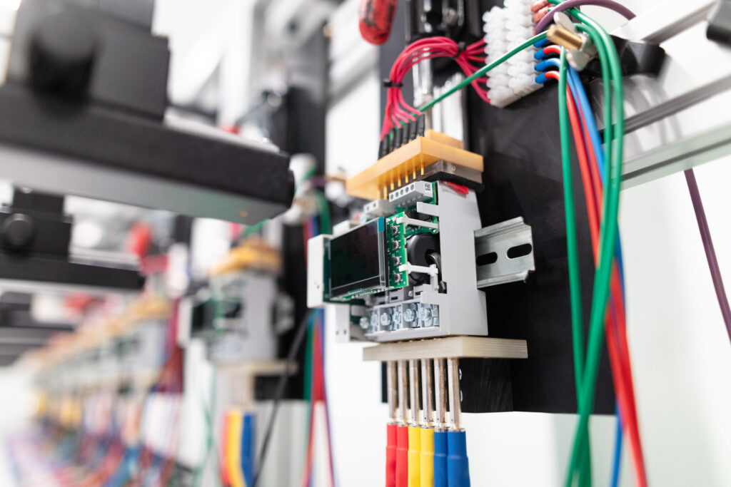
In a three-phase meter, the challenge intensifies. The voltage between phases is higher than phase-to-neutral, and the PCB must accommodate three independent current paths plus neutral, all within the dimensional constraints of a DIN-rail enclosure. Every millimetre of board layout carries consequences for safety compliance.
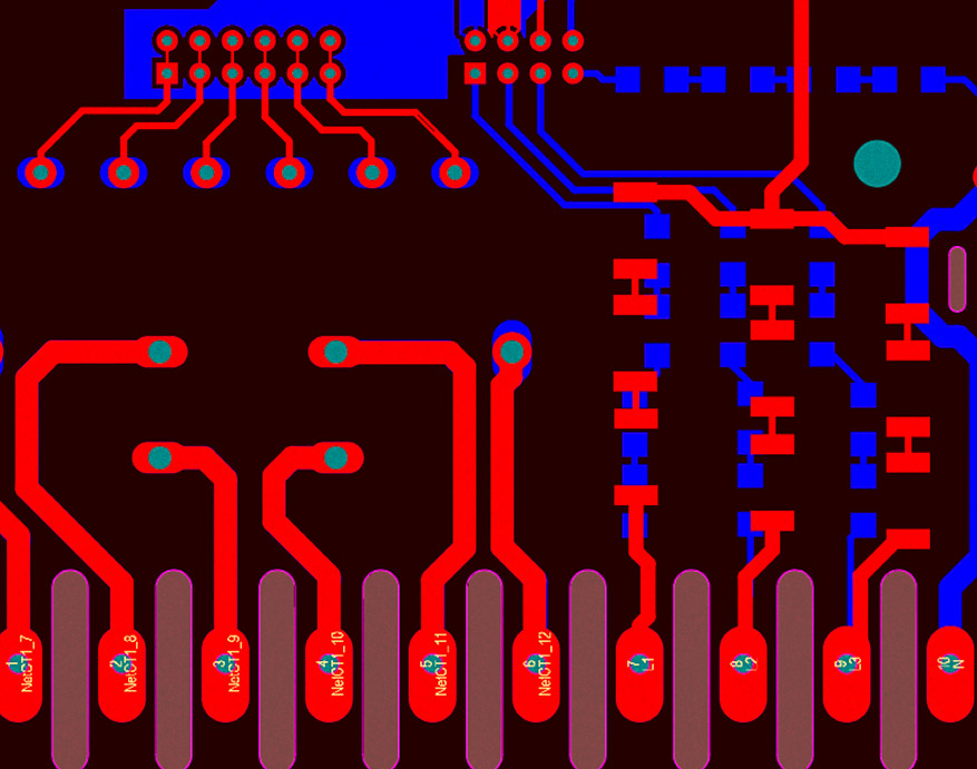
The choice of insulation class (functional, basic, supplementary, or reinforced) defines how many layers of protection stand between the user and a fault. Reinforced insulation, required where no protective earth is available, demands the strictest creepage and clearance values and often forces the designer to rethink component placement entirely.
Fault protection: what happens when something breaks
Safe operation under normal conditions is only half the requirement. The design must also guarantee safety when things go wrong.
If insulation degrades or a short circuit occurs, the system must interrupt fault currents before they cause damage or danger. This demands correctly rated fuses or equivalent protective devices, coordinated with the maximum prospective fault current of the installation.
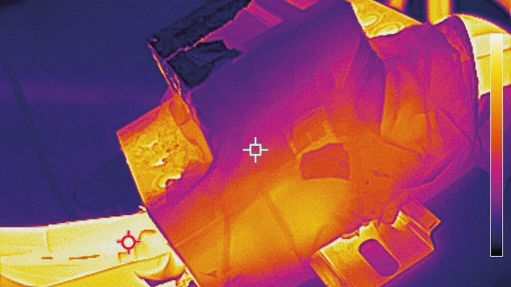
Transient overvoltages, from lightning, switching events, or grid disturbances, require dedicated suppression. Metal oxide varistors and transient voltage suppressors are standard tools, but their selection depends on the specific voltage category and the energy levels the meter must withstand. Undersizing these components does not show up in routine testing. It shows up in the field, under surge conditions, as a failure.
Material selection intersects directly with fault protection. Insulating and structural plastics must meet flammability requirements: UL94 ratings are not optional specifications, they are gatekeeping criteria for certification. A plastic enclosure that burns instead of self-extinguishing turns an electrical fault into a fire.
Leakage current: the invisible risk
Every meter with EMI filtering introduces a path for leakage current: small currents that flow to earth through filter capacitors under normal operating conditions. These currents are by design, but they must remain within strict limits.
The acceptable threshold depends on the equipment class and intended installation. In portable or plug-connected equipment, the limits are tighter. In permanently connected industrial meters, slightly more leakage is tolerable, but still regulated.
What makes leakage current dangerous is its subtlety. The meter works. No fault has occurred. But if the leakage exceeds the threshold, the product is non-compliant, and under certain fault conditions, it becomes a shock hazard.
The regulatory landscape: not one standard, but three conversations
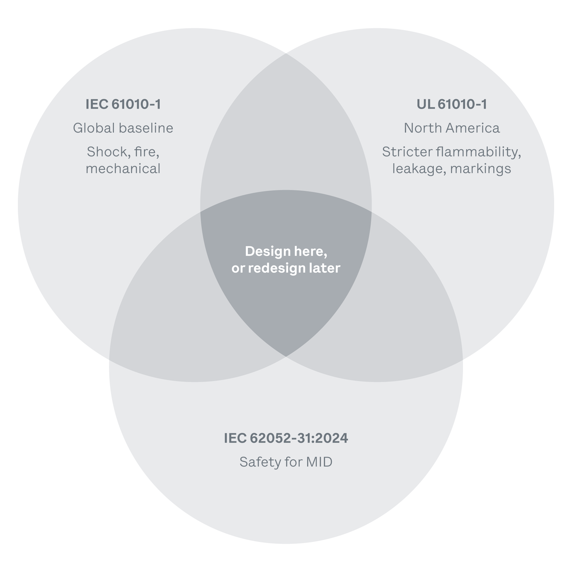
An OEM integrating a meter into a product destined for multiple markets is not dealing with a single safety framework. There are at least three normative conversations happening simultaneously, and they do not always agree.
IEC 61010-1 is the global baseline. It defines protection against electric shock, fire, and mechanical hazards, with voltage parameters flexible enough to cover most international grid architectures. For the European market, this is typically the starting point.
UL 61010-1 is its North American counterpart: similar in structure, but stricter in specific areas. Flammability ratings are more demanding. Leakage current limits for high-humidity industrial environments are tighter. Safety markings must follow North American conventions. A design that passes IEC may not pass UL without modifications, and those modifications can ripple through the entire board layout.
Then there is IEC 62052-31:2024, the most recent and arguably the most consequential update. This standard, specific to metering equipment, extends the voltage scope up to 1500V DC and introduces explicit requirements for direct current systems and electric vehicle supply equipment. For any OEM building EV charging infrastructure, battery storage systems, or DC-coupled solar inverters, this standard is no longer optional reading. It redefines what a compliant meter must withstand in terms of insulation, impulse voltage, and thermal endurance at voltage levels that previous metering standards simply did not contemplate.
The practical consequence for an OEM: a meter designed exclusively to IEC 61010-1 may be perfectly safe for a traditional AC installation, but structurally inadequate for a 1000V DC string in a photovoltaic system or an 800V DC bus in an EV fast charger. The safety architecture must be designed with the target application in mind from the start not retrofitted after the first certification attempt fails. Discovering a normative gap during certification does not mean a two-week fix. It means months of redesign, retesting, and requalification. The cost is not in engineering hours. It is in lost time-to-market.
What this means at the supplier level is straightforward. Your meter partner must be fluent in all three frameworks simultaneously, and able to anticipate where they diverge. A supplier who designs to one standard and hopes the others will follow is a supplier who will cost you time.
Validation: proving the design, not assuming it works
Safety cannot be simulated into existence. It must be proven through physical testing.
Dielectric strength testing (hipot) applies high voltage between isolated circuits to verify that insulation holds under stress beyond normal operating conditions. Protective earth continuity testing confirms that the grounding path can carry fault current without excessive impedance. Single-fault condition testing deliberately introduces failures to verify that no single point of failure creates a hazard.
These tests are not one-time events. They are performed on every production unit, and any design change (even a component substitution) can invalidate previous test results and require requalification.
What this means for the OEM
If you are specifying an energy meter for integration into your system, the safety engineering inside that meter becomes part of your product’s safety chain. The supplier’s design choices on isolation, fault protection, and material selection directly affect your ability to certify and ship.
The question is not whether your meter supplier has a CE or UL mark. The question is whether they understand the engineering behind it deeply enough to maintain compliance when you ask for a custom variant, a different voltage range, or a modified enclosure, and whether they can do it across IEC, UL, and the new DC-extended requirements of 62052-31 without starting from scratch.
A supplier fluent in IEC, UL, and the DC-extended scope of 62052-31 does not just reduce your compliance risk. It protects your launch timeline. Every variant, every voltage change, every market extension that does not require a full redesign is time you keep.
That depth is not visible on a datasheet. It is visible in the conversation.