Current Sensors in Energy Meters: Shunt, CT, Rogowski, Hall Effect. Why the measurement front end defines the entire design
A project often starts with specifications that seem perfectly clear: measure three-phase current up to 80 A, achieve Class 1 accuracy, and provide enough bandwidth to cover harmonics up to the 25th order. A shunt is selected. The prototype works. The meter gets certified. Twelve months later, the same project needs to support a version for an 800 V DC bus, or an EV customer asks for a bidirectional variant with microamp resolution in standby, or an industrial OEM wants to extend the range to 400 A. At that point, there is no incremental fix left. The measurement front end has to be redesigned from the ground up.
Current sensing technology is not just one component among many. It is the architectural choice that determines, for the entire commercial life of the product, which applications the meter can serve and which it cannot.
Four technologies, four different physical regimes
There are four main technologies for current measurement in an energy meter: resistive shunt, current transformer (CT), Rogowski coil, and Hall-effect sensors in their open-loop, closed-loop and fluxgate variants. Each is based on a different physical principle, and each principle brings constraints and opportunities that no downstream optimization can fundamentally change.
A shunt measures the voltage drop across a known resistance: it is the most direct method and, within its limits, the most accurate. A CT relies on Faraday’s law: a ferromagnetic core couples primary and secondary, providing galvanic isolation by design, but at the cost of saturation. A Rogowski coil is effectively a CT without a core: eliminating the ferromagnetic material removes saturation, but requires signal integration downstream. Hall-effect sensors measure the magnetic field generated by the current, and they are the only family of technologies that natively works with DC.
None of these technologies is universally superior. The choice depends on four application parameters: current regime (AC, DC, bidirectional), required bandwidth, required isolation level, and the combination of accuracy and thermal stability expected over the entire product lifetime.
Resistive shunt: simplicity comes at a price
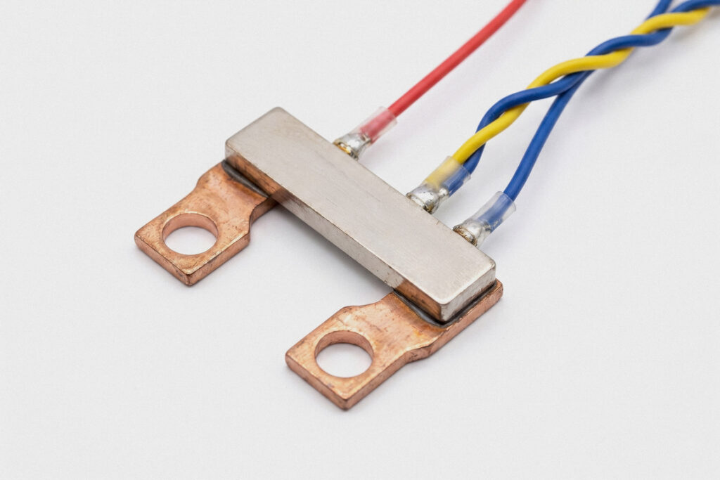
A shunt is a calibrated resistor, typically between 50 µΩ and 500 µΩ for standard line currents, that generates a voltage drop proportional to current according to Ohm’s law. The resulting measurement signal is in the millivolt range and is digitized by a high-resolution ADC, usually after a fixed-gain amplification stage.
The main advantage of the shunt is its exceptional linearity. It does not saturate, has no hysteresis, and its bandwidth is limited only by the component’s parasitic inductance, which is typically negligible below 100 kHz. It is naturally bidirectional: the voltage across it changes sign when current reverses direction. It is also the most cost-effective solution for low to medium current ranges.
Its limitations are twofold, and both become critical very quickly in real applications.
The first is thermal dissipation. Power dissipated in the shunt follows P = I²R. A 500 µΩ shunt carrying 80 A dissipates 3.2 W in a component only a few square millimeters in size. That heat changes the resistance according to the material’s temperature coefficient (TCR), introducing a measurement error that room-temperature calibration cannot remove. Specialized alloys such as Manganin or Zeranin reduce TCR to values between 1 and 15 ppm/°C, but they do not eliminate the issue. In a Class 1 meter, a 40°C thermal gradient across the shunt can by itself introduce an error between 0.04% and 0.6%, depending on the material.
The second limitation is the lack of galvanic isolation. The shunt sits in series with the line conductor, so the measurement node is at line potential. Every downstream stage, amplifier, ADC, microcontroller, must therefore be isolated separately, typically with capacitive isolated amplifiers or digital isolators, and powered by an isolated DC-DC converter. This increases complexity, cost, PCB area, and introduces additional noise sources that the EMC layout must control.
Current transformer: native isolation and its limits
A CT is a transformer with a defined turns ratio whose primary is the line conductor itself. The secondary, isolated through the ferromagnetic core, delivers a reduced current proportional to the primary current. Galvanic isolation is built into the topology: no additional isolation component, no dedicated support circuitry.
That single advantage largely explains why CTs remain the dominant technology in high-current three-phase industrial meters and power distribution systems. The secondary current is passed through a low-value burden resistor, and from that point onward the measurement chain proceeds much like a shunt-based design, but at ground potential.
All CT limitations come from the physics of the ferromagnetic core.
The first is saturation. A DC offset in the primary current, even a modest one, biases the core toward saturation and destroys linearity in the AC waveform superimposed on it. This is why conventional CTs perform poorly in applications involving UPS systems, poorly designed inverters, half-wave rectifier loads, or inrush transients with residual DC content.
The second limitation is directionality. A standard CT does not directly detect the sign of the current except through the phase of the secondary signal. Supporting bidirectional measurement therefore requires dedicated front-end electronics and accurate phase calibration, which is not trivial in three-phase multifunction meters measuring active, reactive, and apparent power separately.
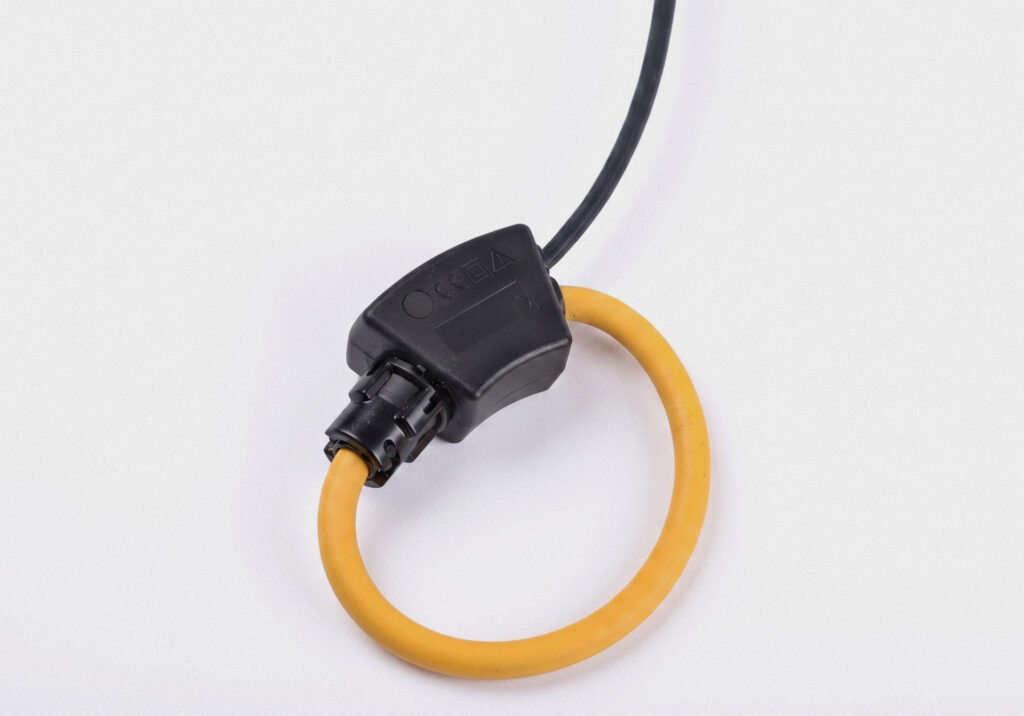
Rogowski coil: wide bandwidth, no saturation
A Rogowski coil is a helical winding without a ferromagnetic core, arranged in a loop around the primary conductor. By Ampère’s law, it generates a voltage proportional to the time derivative of the current, dI/dt. Its analog output must therefore be integrated, actively or passively, to reconstruct a signal proportional to current.
By removing the core, the Rogowski coil eliminates the main limitations of the CT in one step: there is no saturation, and the response remains linear over current ranges that can span five orders of magnitude. Bandwidth typically extends from 0.1 Hz to beyond 1 MHz with excellent linearity. A single Rogowski sensor can measure currents from 1 A to 10 kA with high accuracy, something no conventional CT can match.
These benefits come at a price.
The output signal is intrinsically weak, and because it is proportional to dI/dt, signal amplitude collapses at low frequency. The downstream integrator must therefore be stable near DC, with tightly controlled offset and thermal drift, otherwise it introduces errors that accumulate over time. The accuracy of the entire measurement chain depends as much on the quality of the integrator as on the quality of the coil itself.
The second limitation is positioning. A Rogowski coil is sensitive to the position of the primary conductor inside the loop: shifts of just a few millimeters can produce significant measurement error. That makes Rogowski coils less suitable for permanent industrial metering solutions, where precise mechanical positioning is not always guaranteed, and much more suitable for portable instruments, retrofit applications, and cases where wide bandwidth justifies the added complexity.
Like the CT, the Rogowski coil cannot measure DC.
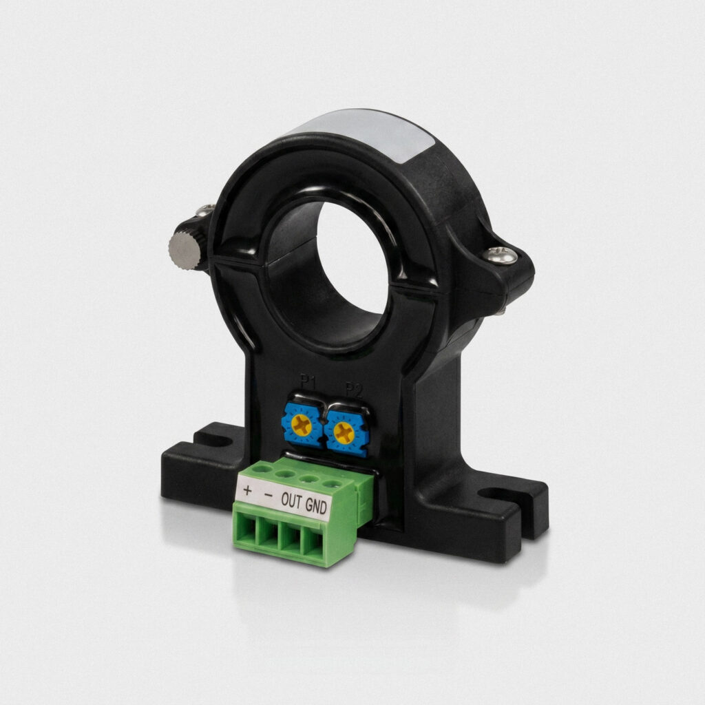
Hall effect and fluxgate: when DC becomes part of the design
When the application requires DC current measurement, in EV charging, photovoltaic strings, or battery storage systems, neither isolated shunt, nor CT, nor Rogowski offers a clean architectural solution on its own. Magnetic-field-based sensors are the only family that combines native DC measurement with galvanic isolation. In industrial practice, there are three main topologies, and the differences between them are substantial.
An open-loop Hall sensor directly measures the magnetic field in the air gap of a concentrating core using the Hall effect. It is the most economical solution and the one with the lowest power consumption, with bandwidth up to roughly 100 kHz. Its main limitation is thermal offset: a typical open-loop Hall sensor has a residual offset on the order of ±1% of full scale, varying with temperature, which makes it unsuitable for revenue-grade metering. It is, however, appropriate for monitoring, overcurrent protection, and low-resolution charge-control functions.
A closed-loop Hall sensor, also known as a zero-flux sensor, adds a compensation winding driven in feedback, canceling the magnetic flux in the core and keeping the Hall element near its optimal operating point. Accuracy improves significantly, typically to Class 0.5, but at the expense of higher power consumption and greater circuit complexity.
Fluxgate is a different technology altogether. It uses a magnetic core alternately driven into saturation by an excitation signal and exploits the harmonic distortion caused by residual DC field as the measurement signal. Among commercially available architectures, it offers the highest accuracy: Class 0.1 performance and thermal offsets significantly lower than those of closed-loop Hall sensors. The trade-off is higher power consumption, significantly higher unit cost, and more complex signal-conditioning electronics.
For an OEM developing DC charging infrastructure for Eichrecht compliance, or a DC meter for storage systems with billing functionality under IEC 62053-41, the real choice is not between open-loop Hall and closed-loop Hall. It is between a correctly dimensioned fluxgate and an alternative architecture based on a digitally isolated shunt with an isolated sigma-delta amplifier. Both approaches can reach the required accuracy class, but with different trade-offs in cost, power consumption, and thermal behavior. The right decision depends strictly on the application’s operating profile.
Choosing for the real application
No current sensor is intrinsically superior. Each has a domain where it is the right choice, and other domains where forcing it into the design will predictably create cost, complexity, and performance problems.
Every choice has downstream consequences: analog front-end topology, number of isolated ADC channels, power budget, calibration strategy, and metrology firmware complexity. A project that chooses the right sensor reduces the complexity of everything that follows. A project that chooses the wrong one pays for that decision in every subsequent layer, all the way to end of life.
What this means for an OEM
When an OEM specifies an energy meter for a given application, current sensing technology is not a detail to leave to the supplier without discussion. It is the decision that determines whether the meter will measure the real current profile of the application with the required accuracy across the entire commercial life of the product.
A supplier proposing a shunt-based solution for an EV DC application is simplifying their own problem, not yours. A supplier proposing a standard CT for an application with VFD loads is pushing harmonic measurement errors downstream. A supplier proposing an open-loop Hall sensor for MID billing applications is under-designing accuracy before the project has even begun.
The question to ask a supplier is not: “What current sensor do you use?” The right question is: “We have this current profile, AC or DC, bidirectional or not, typical range and peak, expected harmonic content, required accuracy, required isolation, operating temperature. Which sensing technology do you recommend, and why did you rule out the alternatives?”
A supplier who can answer that in a structured way, recommended technology, technical rationale, alternatives considered, trade-offs accepted, has done the engineering work you actually need. A supplier who offers one sensing technology for every application is selling what they have, not what your project requires.
The choice of current sensor defines the meter. That is why any serious evaluation of an OEM energy metering supplier starts with this question, not with a catalog code.